Optical filters are employed in imaging equipment to adjust image brightness, enhance picture contrast, and within the overall optical system to transmit or reflect specific wavelengths, or to split a single beam of light into two or more independent wavelengths. Various filters are available to suit different applications. To aid understanding of filters, the necessary terminology is explained below.
Table of Contents
1. Glossary of Optical Filter Terms
・ Bandpass filter
・ Centre wavelength (CWL)
・ Bandwidth (FWHM)
・ Blocking
・ Transmission
・ Slope
・ Optical density (OD)
・ Cut-on
・ Cut-off
2. Types of Optical Filters
・Absorption-type and Non-absorption-type
・Dichroic Filter
・ND Filter
・IR Cut Filter
・Bandpass Filter
・Notch Filter
・Excitation Fluorescence Filter
・SWIR Filter
・Raman Spectrometer Filter
・ LIDAR Filter
3. Differences Based on Optical Filter Fabrication Methods
・Soft coating
・Hard coating
・Deposition method
・Sputtering method
4. Differences Based on Wavelength
・Visible light
・Near-infrared
・Infrared
1. Glossary of Optical Filter Terms
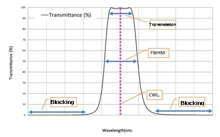
・Bandpass Filter
A bandpass filter is an optical filter that transmits only a specific wavelength band. Key elements for bandpass filters are the centre wavelength and bandwidth. These are explained below.
・Centre Wavelength (CWL)
The numerical value at the centre of the transmitted wavelength band. This is often taken as the midpoint of the bandwidth described below. CWL: Centre Wavelength
・Bandwidth (FWHM)
The wavelength width between the short-wavelength side and long-wavelength side where the transmission reaches 50% of the maximum transmission within the transmitting wavelength band. FWHM: full width at half maximum.
Product Introduction: Band pass filter, multiple band pass filter
・Blocking
The blocking refers to the wavelength region where the filter blocks transmission. The degree of transmission blocked is specified either by transmission percentage (e.g., 1% or less) or by the optical density (OD) value described later. This is one of the key metrics when evaluating optical filters.
・Transmission
Conversely, this is the wavelength where the filter does not block light. It is specified by the degree of transmission, such as 80% or more.
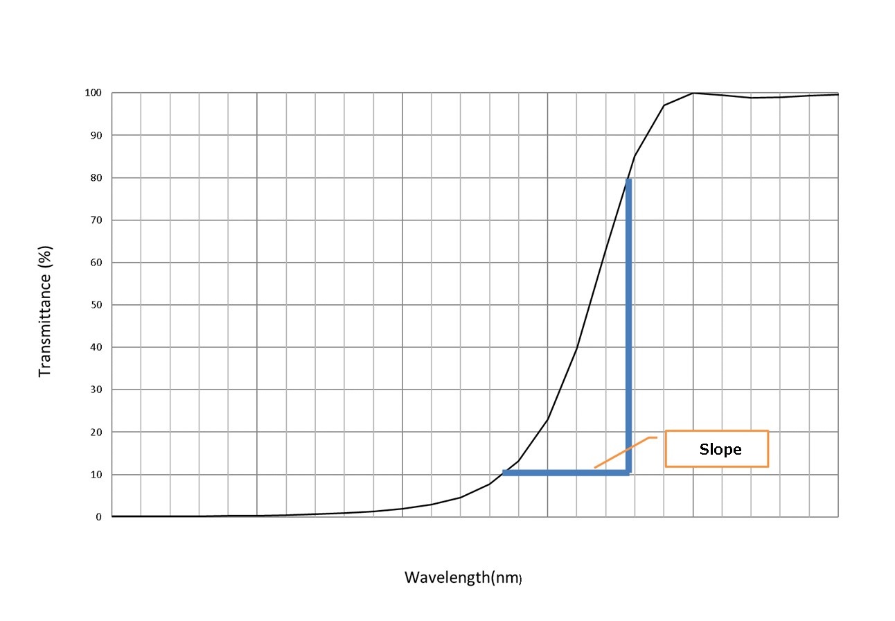
・Slope
The slope is a specification defined for edge filters (filters possessing transmission and reflection bands that switch at relatively narrow wavelength widths) and bandpass filters. It represents the wavelength bandwidth required for the transition from the blocking region to the transmission region. The transmittance defining the slope magnitude is unrestricted. However, it is commonly standardised using the bandwidth from the 10% transmittance point to the 80% transmittance point.
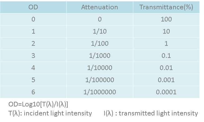
・OD (Optical Density)
The OD (optical density) represents the amount of energy blocked from transmission. A higher OD results in lower transmittance, while a lower OD yields higher transmittance. Filters with an OD of 6.0 or higher are used in Raman spectroscopy and excitation fluorescence filters, where extremely high blocking performance is required. OD of 3.0–4.0 are used in filters for machine vision and chemical detection. Filters with an OD of 2.0 or below are used for colour sorting and imaging equipment applications.
Product Introduction: ND Filters
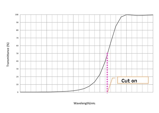
・Cut-on
The cut-on wavelength indicates the wavelength at which the transmittance reaches 50% for a long-pass filter. The cut-on wavelength is also denoted as λcut-on.
Product Introduction: Long-pass filter
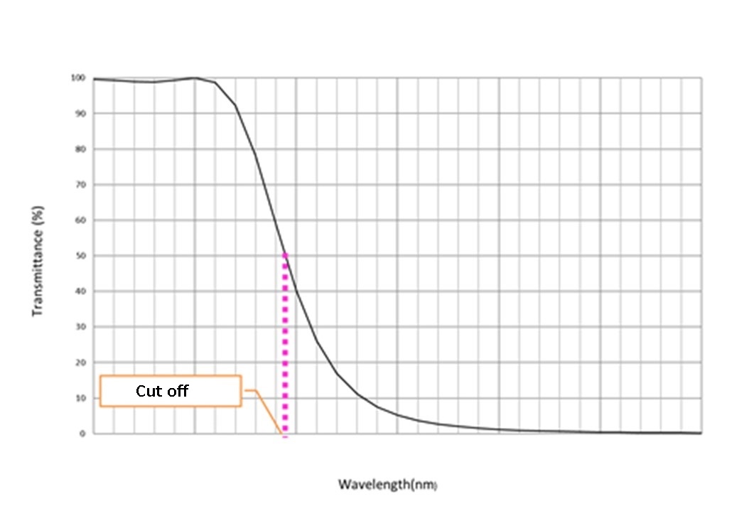
・Cut-off
The cut-off wavelength indicates the wavelength at which the transmittance drops to 50% in a short-pass filter. The cut-off wavelength is also denoted as λcut-off.
Product Introduction: Short-pass filter
2. Types of Optical Filters
・Absorption Type and Non-Absorption Type
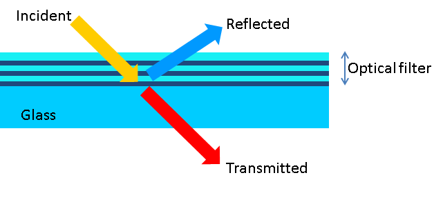
Optical filters are broadly categorised into absorption type and non-absorption type (interference type).
・Absorption Type
Characterised by absorbing and blocking a portion of the incident light, allowing only specific light to pass through. It is less prone to unnecessary light becoming noise and is a filter that does not require as much concern over the angle of incidence as the interference type. Another advantage is their relatively low cost. Conversely, a disadvantage is that the boundary of the selected wavelength band is not sharp, resulting in somewhat inferior selectivity.
Product Introduction: ND Filter
・Non-Absorptive (Interference) Type
These primarily utilise a multilayer structure of metal oxide films, employing light refraction to achieve the filter’s characteristics. Unlike absorptive types, they exhibit strong angle dependence; unless used at the designed incidence angle, they cannot perform as specified. They offer high flexibility in spectral characteristics, enabling steep slopes in specific regions.
Product Introduction: Laser Mirrors
・Dichroic Filters
These filters utilise light interference to transmit or reflect specific bands. They are constructed by layering dielectric thin films onto substrates, primarily glass or highly transparent resin materials. They are suitable for R・G・B spectral separation and synthesis. This is a general term for filters that transmit only specific wavelength bands while reflecting others.
Applications: CCD imaging, projectors, infrared sensors, ToF sensors, and various others.
Product Introduction: Dichroic Filter
・ND Filter
ND stands for Neutral Density. This filter reduces light intensity by absorbing a fixed amount within specific wavelength bands. Performance is rated by OD value; a higher OD indicates lower transmittance, while a lower OD indicates higher transmittance.
Applications: Surveillance cameras, video cameras
Product Introduction: ND Filter
・IR Cut Filter
An IR cut filter is an optical filter that transmits visible light while blocking infrared (IR) radiation. It is used to suppress reddish tints in video/imagery or to cut solar heat radiation.
Applications: Projectors, mobile cameras, surveillance cameras
Product Introduction: IR Cut Filter
・Bandpass Filter
A bandpass filter is an optical filter that transmits only a specific wavelength band while blocking wavelengths on both sides (short-wavelength side and long-wavelength side).
Applications: Analytical instruments, medical, astronomy, optical communications, lasers, lighting
Product Introduction: Bandpass Filter, Multiple bandpass Filter
・Notch Filter / Band stop filter
A filter that blocks a specific wavelength band while transmitting other wavelength bands. It possesses the inverse characteristics of a bandpass filter. Also known as a bandstop filter.
Applications: Laser excitation, fluorescence measurement, biomedical, Raman spectroscopy filters
Product Introduction: Notch Filter
・Excitation Fluorescence Filters
Excitation fluorescence observation involves observing the fluorescence emitted when excitation light is applied to a sample stained with a fluorescent dye. Filters used for this purpose are known as excitation fluorescence filters.
Fluorescence filter: A filter that transmits fluorescence emitted from the sample while blocking other light. Since the intensity of fluorescence relative to excitation light is very low, unnecessary excitation light wavelengths must be blocked with a high optical density (OD) value during fluorescence observation.
Excitation filter: A filter that transmits the wavelength required to excite the fluorescent substance while blocking the fluorescence wavelength band. Conversely, if the fluorescence wavelength band is not blocked with a high optical density (OD) value, it becomes impossible to distinguish during fluorescence observation whether the light observed originates from the original light source or is due to fluorescence.
Product Introduction: Fluorescence Analysis Dichroic Filters, Fluorescence Analysis Dichroic Mirror
・SWIR Filters
SWIR light, known short-wave infrared light, is typically defined as light in the 0.9–1.7 μm wavelength range. As the upper sensitivity limit of silicon sensors is approximately 1.0 μm, SWIR imaging previously required sensors capable of performing within the specific SWIR region. However, new SWIR sensors with sensitivity spanning both the visible and SWIR regions have recently been developed, necessitating optical filters tailored to the intended application range. Given the broader sensitivity of these sensors, customised filters with wider blocking bands than conventional filters are required. Filters specifically designed for these new SWIR sensors are collectively termed SWIR filters.
Product Introduction: SWIR Filters
・Filters for Raman Analysers
Raman spectrometers are instruments that detect Raman scattered light from a sample to identify its molecular structure and evaluate its physical properties. Raman spectrometers comprise an excitation light source, a filter to remove Rayleigh scattered light, a spectrometer to spectrally resolve the Raman scattered light, and a detector.
As the intensity of Raman scattered light is very weak, a light source with sufficient intensity to generate adequate Raman scattered light, along with wavelength reproducibility and monochromaticity, is required. Lasers are now commonly used for this purpose. The filter used for detecting this Raman scattered light must block the intense laser light while simultaneously allowing Raman scattered light wavelengths near the laser wavelength to pass through. Consequently, filters for Raman analysis require an extremely steep slope characteristic.
Product Introduction: Raman Filter
・LIDAR Filters
LiDAR stands for ‘Light Detection And Ranging’. LiDAR is a technology that accurately measures the position of objects within its field of view using analysis methods such as Time-of-Flight (ToF) or coherence.
During operation, ambient light (natural light, illumination, etc.) and stray light pose challenges for signal acquisition. Consequently, optical filters are required to separate the LiDAR wavelength from other light.
The characteristics of LiDAR filters are as follows:
・Functioning as a bandpass filter or transmission filter for the measurement wavelength.
・Requiring high transmittance.
・Being a filter with low angle dependence.
・Possessing a high optical density (OD) value in the stopband.
・Demonstrating good environmental performance (temperature, humidity, etc.).
Product Introduction: Low Angle-dependence Bandpass Filter
3. Differences Based on Optical Filter Fabrication Methods
・Soft Coating
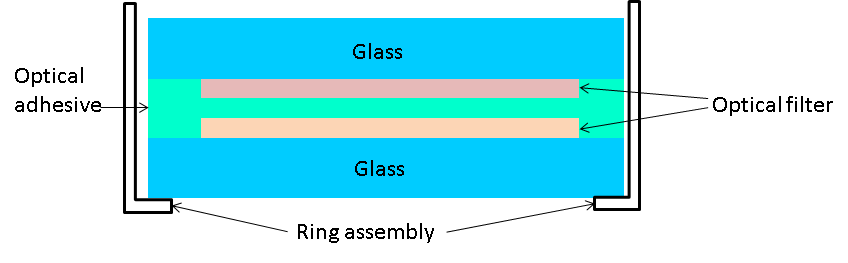
Soft coating involves layering substances such as zinc sulphide or silver as thin films. For conventional soft-coated films, the coating surface is protected by laminating the soft-coated film. In most cases, a protective glass layer is bonded onto the soft-coated film layered onto the glass substrate. The reason for this is that, due to the materials used and the manufacturing process, soft coating does not offer high durability (particularly against moisture).
Costs can be reduced through the low operating costs of the vapour deposition equipment, short product cycle times, and the use of inexpensive float glass substrates. However, the costs associated with work processes such as sealing and the assembly of rings (gold frames) are high. The relationship between cost and production volume is such that costs are high for small quantities, stabilising only after exceeding a certain volume threshold.
Product Introduction: Interference Filter
・Hard Coating
Hard coating involves depositing dielectric materials (primarily metal oxides) using methods such as heating or ion plating, with additional processes to enhance film quality. Compared to soft coating, it offers more uniform film quality, higher packing density, and superior environmental resistance. Furthermore, the wavelength transmission characteristics of hard coating are generally higher than those of soft coating.
Comparing bandpass filters as an example: soft coating exhibits lower transmittance and a gentler slope, whereas hard coating features a steeper slope, higher transmittance, and provides a more stable optical filter.
・Deposition Method
Within a vacuum chamber, the deposition material is heated to vaporise (or sublimate). Deposition refers to the method of forming a thin film by depositing this vaporised material onto the surface of a substrate positioned at a distance within the vacuum chamber.
Depending on the deposition material and substrate type, heating methods include resistance heating, electron beam, high-frequency induction, and laser. Deposition materials comprise metals such as aluminium, chromium, zinc, gold, silver, platinum, and nickel, alongside oxides and fluorides like SiO₂, TiO₂, ZrO₂, and MgF₂.
・Sputtering Method
Sputtering refers to the phenomenon where particles constituting the target are emitted when a positive ion, such as Ar⁺ (argon ion), collides at high speed with the target (primarily a metal plate). The sputtering method utilises this phenomenon, depositing particles from the target to form thin films.
Compared to the evaporation method, the sputtering method offers uniform deposition rates per unit time and superior film thickness control. Furthermore, depending on the size of the target and the chamber, it enables thin film deposition onto large substrates.
4. Differences by Wavelength
・Visible Light
Visible light is emitted by the sun and various other light sources. Typically, it consists of a mixture of visible light rays of different wavelengths, appearing as a colour close to white. Wavelength-wise, it is broadly said to range from approximately 380nm to 780nm. Optical applications are most numerous in this band compared to others, encompassing a diverse range of products from imaging devices like smartphones and projectors, to analytical instruments such as microscopes and measuring equipment, and lighting devices represented by LEDs in recent years. Optical filters are used in many of these, with various customisations made depending on the application.
・Near-Infrared
Near-infrared lies between the visible and infrared regions. In terms of wavelength, this corresponds to 780 nm to 2500 nm. A key characteristic is that most substances absorb very little near-infrared light (though some absorption does occur). Consequently, near-infrared light typically passes through most materials. Furthermore, unlike X-rays or ultraviolet light, near-infrared light has virtually no adverse effects when irradiated onto the human body. It has numerous applications, being widely used in consumer products such as remote controls for televisions and air conditioners, CD players, and in optical communications like fibre optics and wireless digital communication. Naturally, optical filters are incorporated into many products.
Product Introduction: Polymer Filter
・Infrared
Infrared light is an electromagnetic wave with a longer wavelength than visible light but shorter than radio waves. Including the near-infrared region, the wavelength range is 780 nm to 1000 μm. The 2500 nm to 4000 nm (4 μm) range is termed mid-infrared, while 4 μm to 1000 μm is far-infrared. Mid-infrared is used for identifying chemical substances due to the appearance of material-specific absorption spectra, and is also employed in quartz tube heaters. Far-infrared radiation possesses wavelengths longer than the transmission limit of glass. Its primary application lies in products utilising the heating effect of thermal radiation to impart heat to objects. It is employed in heating systems and cooking appliances. Furthermore, it finds use in thermography applications and the field of infrared astronomy.
Within this infrared region, a variety of optical filters are also utilised.
Please feel free to inquire us